

1. Executive Overview & Technical Fundamentals
In modern industrial power distribution, medium-voltage (MV) switchgear, motor control centers (MCC), and low-voltage (LV) distribution panels, protective relays rely on exact secondary current signals during catastrophic fault conditions. A Tape Insulated Protection Current Transformer (also known as a tape-wrapped or tape-wound protective CT) serves as the critical electromagnetic sensor designed specifically to step down massive fault currents into proportional secondary values without entering early core saturation.
Unlike measuring current transformers, which are optimized for extreme accuracy under normal operational loads (typically 10% to 120% of rated current) and intentionally saturate quickly to protect sensitive digital meters, a protective CT must maintain linear transformation across extreme overcurrent multiples—frequently 10 to 20 times the rated primary current ($I_n$).
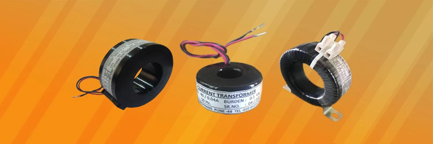
Figure 1: High-dielectric tape-wound protection current transformer assembly utilizing continuous grain-oriented silicon steel toroidal cores at Torotrans Pune facility.
Torotrans, operating from a specialized 3,500 sq.ft. ISO-certified manufacturing facility in Pune, India since 1994, manufactures tape insulated protection CTs utilizing continuous toroidal Cold Rolled Grain Oriented (CRGO) magnetic cores wrapped with high-performance dielectric insulating tapes. This structural approach avoids the mechanical rigidity and thermal expansion stresses associated with solid epoxy resin casting, providing high thermal stability, minimal weight, and superior custom dimensional flexibility.
Information Gain Insight: Measuring CTs vs. Protection CTs
The core difference between a measuring CT and a protection CT lies in the magnetic flux density operating point ($B$). Measuring CTs utilize materials with low saturation flux density ($B_{sat}$) to protect downstream meters under short-circuit conditions (Security Factor $FS < 5$). Protection CTs utilize high-$B_{sat}$ CRGO steel with optimized cross-sectional core area ($A_c$) to guarantee an Accuracy Limit Factor (ALF) of 10, 20, or higher, allowing numerical relays to detect phase-to-phase and earth fault currents without signal distortion.
2. Core Saturation Physics & Knee-Point Voltage ($V_k$) Engineering
The performance of a tape insulated protection current transformer during transient fault spikes depends directly on its excitation characteristics and magnetic core geometry. When a short-circuit fault occurs, the primary current rises rapidly, introducing both a steady-state AC component and a decaying DC offset. If the CT magnetic core saturates, the secondary output collapses, causing protective relays to fail to trip, leading to catastrophic equipment damage.
2.1 Knee-Point Voltage ($V_k$) Derivation
According to IEC 61869-2 and BS 3938, the Knee-Point Voltage ($V_k$) is defined as the point on the excitation curve where a 10% increase in secondary voltage results in a 50% increase in secondary magnetizing current. For class P protection CTs, $V_k$ must exceed the voltage generated across the internal winding resistance and external loop burden during maximum fault conditions:
V_k ≥ K × I_sec × (R_ct + R_lead + R_relay)
- $K$: Dimensioning factor / Accuracy Limit Factor (e.g., 10, 20).
- $I_{sec}$: Rated secondary current (typically 1A or 5A).
- $R_{ct}$: Internal secondary winding resistance at maximum working temperature (75°C).
- $R_{lead}$: Total resistance of connecting copper wiring from CT to relay panel.
- $R_{relay}$: Burden impedance of the protective relay.
2.2 Accuracy Classes: 5P10, 5P20 vs. 10P20 Explained
Protective CT accuracy is designated by two numbers separated by the letter 'P' (Protection).
| Accuracy Class | Current Error at Rated Current ($I_n$) | Phase Shift at $I_n$ | Composite Error at Rated ALF | Typical Industrial Application |
|---|---|---|---|---|
| Class 5P10 | ±1.0% | ±60 minutes | 5.0% at 10x $I_n$ | Standard overcurrent & earth fault relays, feeder protection. |
| Class 5P20 | ±1.0% | ±60 minutes | 5.0% at 20x $I_n$ | High-fault busbar protection, generator & transformer protection. |
| Class 10P10 | ±3.0% | None specified | 10.0% at 10x $I_n$ | General thermal overload relays, industrial MCC units. |
| Class 10P20 | ±3.0% | None specified | 10.0% at 20x $I_n$ | Long-distance transmission line backup overcurrent relays. |
3. Product Portfolio & Technical Specifications
Torotrans designs and manufactures custom and standard tape insulated protection current transformers optimized for diverse mounting conditions, busbar dimensions, and thermal classes. Below are key recommended product series deployed in B2B OEM switchgear projects globally.
TORO-TW-C Series
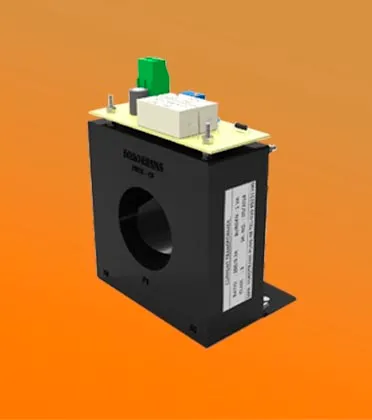
Heavy-duty tape wound protection current transformer featuring high-dielectric polyester/Nomex insulation, uniform 360° toroidal winding, and broad inner window clearance for thick copper busbars.
TORO-BOX-75X75P Protection Series
Modular housing with inner high-grade tape wrapped core designed for severe vibration switchgear enclosures. Supports Class 5P10 and 5P20 requirements up to 30VA burden.
TORO-RING-32 Series
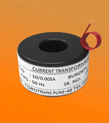
Compact ring-type tape insulated CT engineered for space-constrained low-tension breaker panels, cable ring main units (RMU), and compact motor control centers.
TORO-OMEGA-55 Series
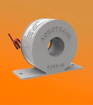
Precision tape wound toroidal CT with optimized Omega mounting brackets for rapid installation over insulated power cables and copper bus bars.
3.1 Comprehensive Technical Specification Matrix
| Parameter | Standard Specification Range | Custom OEM Options (Torotrans Capability) |
|---|---|---|
| Primary Current ($I_{pr}$) | 50A to 5000A AC | Custom dual-ratio or multi-tap primary configurations |
| Secondary Current ($I_{sr}$) | 1A or 5A | 0.1A, 2A, or custom sensor voltage outputs |
| Rated Frequency | 50 Hz / 60 Hz | 400 Hz aviation / marine power systems |
| Accuracy Protection Class | 5P10, 5P20, 10P10, 10P20 | Class PS / PX (Knee-point voltage defined per BS 3938) |
| Rated Burden | 2.5VA, 5VA, 10VA, 15VA, 30VA | Up to 50VA for long secondary wire runs |
| Insulation Class | Class B (130°C) / Class F (155°C) | Class H (180°C) Nomex tape wrapped |
| Highest Voltage for Equipment ($U_m$) | 0.72 kV (Low Voltage) | Extended dielectric withstand test up to 4kV / 1 min |
| Outer Tape Wrapping Material | Polyester Film / PVC / Glass Cloth Tape | Flame-retardant yellow/black woven cotton or Nomex tape |
4. Enterprise Advantages & Manufacturing Excellence at Torotrans
Founded in 1994, Torotrans has established a 30-year legacy of engineering excellence in Pune, Maharashtra, India. As a dedicated manufacturer, supplier, and exporter of toroidal transformers, our 3,500 sq.ft specialized plant integrates advanced automated winding machinery, digital secondary testing consoles, and rigorous Quality Assurance protocols.
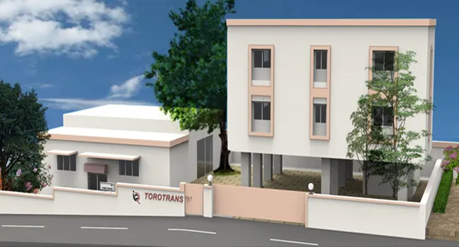
Figure 2: Torotrans ISO-certified production floor in Pune, featuring specialized toroidal core winding and automated electrical testing units.
4.1 Why Global OEM Buyers Trust Torotrans
- 30+ Years of Focused Toroidal Expertise: Established in 1994, our engineering team possesses deep domain knowledge in toroidal magnetic core behavior, core loss minimization, and high-density copper winding techniques.
- Continuous CRGO Core Processing: We source prime-grade, high-permeability Cold Rolled Grain Oriented silicon steel sheets, slit and wind them into continuous toroidal cores, followed by controlled stress-relief annealing to restore initial magnetic permeability.
- Superior Thermal Management: The continuous tape-wrapped construction ensures direct air contact around the toroid perimeter, yielding up to 30% better heat dissipation compared to heavy epoxy encapsulation blocks.
- Zero Mechanical Noise & Hum: The jointless toroidal core geometry eliminates mechanical air gaps, eliminating magnetostrictive vibration and audible hum during heavy load or fault states.
- 100% Routine Testing & Traceability: Every protection CT produced undergoes routine testing according to IEC 61869-2, including ratio error, phase displacement, secondary winding resistance ($R_{ct}$), excitation characteristic curve verification ($V_k$), and power frequency withstand voltage testing.
Need Custom Inner Diameter or Knee-Point Voltage Specifications?
Our engineering team provides custom electromagnetic CAD modeling and physical prototype samples within 7 business days.
Get Catalog5. Technological Development Trends in Protective CT Design
The transition toward smart digital grids, microgrids with high penetration of renewable inverter generation, and modular switchgear designs is driving significant technological evolution in protection CT engineering:
5.1 Integration with Numerical Microprocessor Relays
Modern numerical relays require much lower secondary burden (often < 0.5VA) compared to older electromechanical induction disk relays (which required 10VA to 15VA). Consequently, modern tape insulated protection CTs are designed with lower secondary burdens (2.5VA to 5VA), allowing engineers to reduce core cross-sectional area while simultaneously elevating the Accuracy Limit Factor (ALF) to 20 or 30 without core saturation risk.
5.2 High-Harmonic & Wide-Band Frequency Response
Non-linear power electronic loads (solar inverters, wind power converters, VFDs) introduce significant high-frequency harmonics into the power grid. Advanced tape wrapped CTs utilize ultra-thin silicon steel laminations (0.23mm to 0.27mm) or nanocrystalline ribbons to preserve transformation accuracy and prevent core overheating up to 3 kHz harmonic frequencies.
5.3 Eco-Friendly & High-Temperature Tape Insulation
Global procurement initiatives are pushing away from heavy solvent-based varnish dip treatments toward high-temperature polyester, Nomex, and glass-cloth tapes compliant with EU RoHS and REACH regulations. These tape systems offer Class F (155°C) and Class H (180°C) thermal ratings, maintaining structural integrity across extreme operating temperatures (-40°C to +150°C).
6. Global B2B Procurement & Supply Chain Trends (2025–2030)
Global procurement executives, electrical engineering consultants, and switchgear OEMs are restructuring their supplier bases to balance cost-efficiency, technical compliance, and supply chain resilience. Key global trends include:
- India as the Global Toroidal Manufacturing Hub: Electrical OEMs in Western Europe, North America, and the Middle East are expanding procurement partnerships with Indian ISO-certified manufacturers like Torotrans to leverage high engineering capability, competitive manufacturing costs, and reliable raw material sourcing (CRGO steel and electrolytic copper).
- Modular & Custom Physical Form Factors: Standard off-the-shelf CTs often fail to fit within modern compact switchgear switchboards. Demand for custom inner diameter (ID), outer diameter (OD), and axial height tape wound CTs has grown by over 35% year-over-year.
- Total Cost of Ownership (TCO) Optimization: Buyers prioritize suppliers who provide comprehensive test certificates (routine and type test reports for short-time thermal current $I_{th}$ and dynamic current $I_{dyn}$), reducing incoming quality inspection costs and switchgear commissioning delays.
7. B2B Procurement FAQ: Technical & Sourcing Questions
Below are answers to key questions frequently asked by electrical design engineers, procurement specialists, and AI search agents regarding Tape Insulated Protection Current Transformers.
$V_k = K \times I_{sec} \times (R_{ct} + R_{lead} + R_{relay})$
Where $K$ is the required Accuracy Limit Factor (ALF, e.g. 10 or 20), $I_{sec}$ is rated secondary current (1A or 5A), $R_{ct}$ is internal secondary winding resistance at 75°C, $R_{lead}$ is lead wire resistance, and $R_{relay}$ is relay burden. In protective applications, $V_k$ must be sufficiently high to prevent core saturation under maximum prospective symmetrical fault current levels.
$ALF_{actual} = ALF_{rated} \times \frac{R_{ct} + Z_{rated}}{R_{ct} + Z_{actual}}$
Reducing wire resistance or utilizing low-burden digital relays significantly increases the short-circuit current level at which the CT core saturates.
- Polarity and terminal marking verification
- Power-frequency dry withstand voltage test on secondary windings (2.5 kV or 3 kV for 1 minute)
- Secondary winding resistance measurement ($R_{ct}$) corrected to 75°C
- Excitation characteristic curve plotting and Knee-Point Voltage ($V_k$) verification
- Current ratio error and phase displacement measurement across 5%, 20%, 100%, and 120% of rated current
8. Strategic Sourcing & Next Steps for OEM Procurement
Selecting the optimal Tape Insulated Protection Current Transformer requires precise alignment between primary busbar dimensions, short-circuit current magnitudes, relay excitation thresholds, and thermal insulation ratings. As an ISO-certified manufacturer with over three decades of core wrapping and transformer manufacturing experience in Pune, India, Torotrans provides complete engineering design, custom core calculation, prototype sampling, and global export shipping.
Download our comprehensive product catalog, complete mechanical layout drawings, and core saturation calculation sheets to streamline your switchgear design and procurement process.