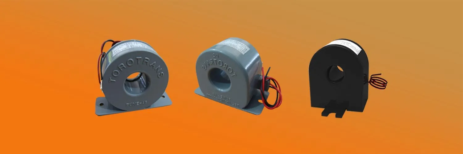
Expert guides, technical updates, and industry insights on Current & Power Transformers.
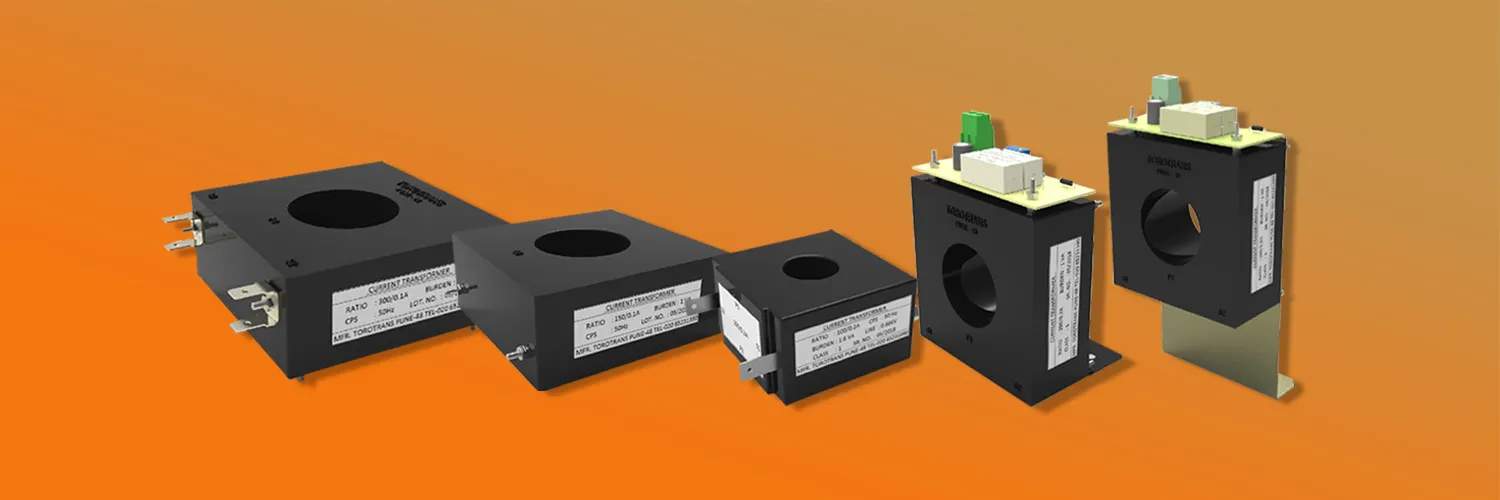
In-depth guides on high-accuracy resin cast measuring current transformers.
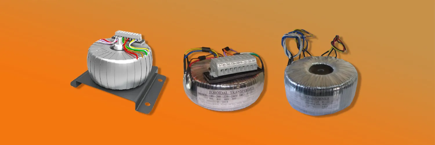
Articles detailing compact, low-noise toroidal power transformers for OEM applications.
Selecting the right Tape Insulated Protection Current Transformer is a practical engineering decision, not a simple brand exercise. These transformers support dependable relay operation during faults, overloads, and abnormal grid conditions. Their tape insulation also influences dielectric strength, thermal endurance, manufacturing consistency, and long-term service confidence.
Stan Zocholl, a respected power-system protection specialist, wrote, “The current transformer is the window through which the relay sees the power system.” That observation remains highly relevant. A relay can only respond accurately when the transformer reproduces primary current faithfully. Small errors can matter. Saturation, burden mismatch, poor insulation, and inadequate testing may distort the protection picture.
This Top 10 Tape Insulated Protection Current Transformer Brands overview examines manufacturers through engineering and purchasing perspectives. It considers ratio accuracy, protection-class performance, insulation construction, short-time thermal current, mechanical strength, testing practices, documentation, and field support. It also considers application details, such as a dusty substation, a crowded switchgear cabinet, or a transformer bay exposed to repeated fault stress.
Brand reputation helps, but it cannot replace technical verification. A famous supplier may still be unsuitable for a specific burden or fault level. That is an uncomfortable point. Product data can look complete while leaving important application questions unanswered.
The ranking should therefore be treated as a research starting point, not a final specification. Engineers should compare test reports, standards compliance, installation conditions, and lifecycle support before approving any Tape Insulated Protection Current Transformer for service. Reliable protection begins with careful details. Sometimes, the smallest detail decides.
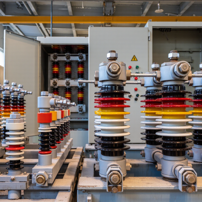
This review covers the top ten tape-insulated protection current transformer manufacturers for demanding power-system applications. The scope includes medium- and high-voltage CTs used with protective relays, circuit breakers, and substations. We examine indoor and outdoor designs, single-core and multi-core arrangements, and custom ratios for different fault levels.
Field experience matters. We compare accuracy class, rated burden, short-time thermal current, and dynamic withstand performance. We also inspect insulation thickness, tape uniformity, creepage distance, and resistance to moisture. A clean datasheet is not proof. Independent test reports and routine production records provide stronger evidence. Where available, compliance with IEC 61869-2 supports a more reliable comparison.
The evaluation also considers manufacturing consistency across repeated orders. Small ratio errors can affect relay operation during severe faults. We therefore look for documented calibration methods, traceable testing equipment, and clear acceptance criteria. Technical support matters when drawings change late. Delivery control matters too. Delays can disrupt a planned panel assembly. Our ranking weighs engineering capability, product durability, test transparency, customization, service response, and total ownership value. The weighting is useful, but not perfect. Site conditions differ, and some published claims need closer verification. Real installations may reveal weaknesses that laboratory data misses.
This chart presents a brand-neutral evaluation framework for tape-insulated protection current transformers. The criteria reflect commonly assessed requirements in IEC 61869-1, IEC 61869-2, and IEEE C57.13. The percentages are assessment weights rather than company or brand performance data.
When comparing tape-insulated protection current transformer manufacturers, IEC 61869-2 accuracy classes deserve close attention. The label often tells more than marketing language. A designation such as 5P10 combines a protection class with an accuracy limit factor. The number before “P” indicates the maximum composite error, while the final number indicates the rated accuracy limit factor.
A 5P class permits a composite error of up to 5% at the specified accuracy limit current. A 10P class permits up to 10%. Lower error generally supports more dependable relay operation, especially during heavy faults. However, 5P is not automatically better for every installation. Burden, winding resistance, cable length, and actual fault current can change performance. I have seen calculations look acceptable until long secondary wiring was included.
Composite error combines current-ratio and phase-related inaccuracies under protection conditions. It is not the same measurement as ordinary metering accuracy. For example, a 5P10 transformer should maintain its stated limit through ten times rated primary current, within the declared burden. A 10P20 extends the current range but allows greater error. That trade-off requires engineering judgment.
For tape insulation, production quality also matters. Evenly applied insulation, controlled drying, and careful terminal assembly reduce avoidable variation. Test reports should show burden, excitation behavior, ratio error, and composite error. Some specifications still list only the class label. That is incomplete. A practical review should compare the declared values with relay requirements, installation distance, and short-circuit studies. Mistakes happen when a familiar class is selected without checking the complete circuit.
A reliable top-ten comparison should examine performance data, not catalogue appearance. Tape-insulated protection current transformers need stable insulation, accurate ratios, and predictable saturation behavior. Rated burden is critical. It includes the relay, test links, terminal blocks, and lead resistance, not only the relay input. A 15 VA transformer may fail its accuracy target when long copper leads consume several volt-amperes.
Accuracy Limit Factor, or ALF, shows how many times rated primary current the transformer can reproduce within its specified protection error. An ALF of 10 sounds adequate, but the real result depends on rated burden and actual circuit impedance. A protection engineer should verify the class, such as 5P or 10P, and check the manufacturer’s test conditions. Small details matter.
Fault current performance requires more than a high ALF number. During a fault, secondary voltage rises sharply, and the core may saturate. Knee-point voltage, secondary resistance, remanence, system X/R ratio, and lead length influence the waveform. For example, a 1000/5 A transformer with a 15 VA burden can behave differently after several metres of undersized wiring. I have seen neat selection tables hide this risk. The ranking is therefore useful only when test certificates, burden calculations, and actual protection settings are reviewed together. Some field conditions remain uncertain.
Top 10 Tape Insulated Protection Current Transformer Brands
Tape-insulated protection current transformers require disciplined testing, not attractive catalog specifications. IEEE C57.13 defines performance expectations for instrument transformers used in North American systems. IEC 61869-2 addresses current-transformer requirements within the IEC framework. Their terminology and test procedures differ, so engineers should not treat them as interchangeable. Check the declared standard, rated frequency, insulation level, accuracy class, and thermal limits before procurement.
Routine testing commonly includes winding resistance, ratio error, polarity, phase displacement, and excitation characteristics. Burden verification is essential because an overloaded secondary circuit can distort fault-current reproduction. Dielectric tests examine insulation strength, while impulse testing may apply to the specified design category. For tape insulation, inspectors should examine winding uniformity, resin condition, clearances, and visible damage near terminals. Small defects matter.
Traceable instruments and calibrated test equipment support reliable results. Test records should identify temperature, applied voltage, burden, test method, and acceptance limits. Independent laboratory review can expose inconsistent measurements between factory and site. A passing ratio test alone proves little. It does not confirm every protection duty.
There is room for doubt.
Real installations can differ from laboratory conditions. Moisture, vibration, wiring resistance, and aging may change performance. Engineers should compare certified reports with field measurements and relay requirements. That extra review is slower, but it reduces assumptions. One overlooked secondary connection can undermine an otherwise compliant transformer.
Top 10 Tape Insulated Protection Current Transformer Brands
Brand Profiles: Insulation Design, CT Ratios, Applications, and Support
The top ten tape-insulated protection CT suppliers differ in construction, ratios, and field support. Their products commonly use layered polyester, paper, or polyimide tape around a toroidal core. This design controls dielectric stress and supports compact switchgear layouts. IEC 61869-2 remains a key reference for protection-class current transformers. Typical ratios range from 50/5 A to 3000/5 A, depending on feeder, generator, or transmission applications. Class 5P20, 10P20, and PX designs appear frequently in relay protection systems. The best profiles explain knee-point voltage, excitation current, insulation testing, and short-time thermal ratings clearly.
MarketsandMarkets’ 2024 current transformer study identifies grid expansion and digital substations as major growth drivers. The IEA’s Electricity Grids and Secure Energy Transitions report estimates annual grid investment must exceed 600 billion dollars by 2030. That pressure increases demand for reliable measurement hardware. Still, a polished datasheet cannot replace site experience. A ratio table may look exact, while saturation behavior changes under real fault conditions. Support quality also matters. Fast engineering replies, test certificates, replacement guidance, and commissioning assistance can prevent costly delays.
Tips: Match the CT ratio to the actual load, not only the transformer nameplate. Check burden, knee-point voltage, insulation level, and cable space together. Ask for test curves. A lower ratio may improve sensitivity, but it can saturate sooner. Some procurement decisions remain imperfect; review them after commissioning.
| Profile | Tape Insulation Design | Typical Insulation System | Common CT Ratios | Protection Classes | Typical Secondary Burden | Operating Voltage Range | Typical Applications | Engineering and Support Features |
|---|---|---|---|---|---|---|---|---|
| Profile 01 | Layered polyester or polyimide tape wrapped directly over the magnetic core with controlled overlap and a grounded electrostatic shield. | Dry-type, resin-supported tape insulation; suitable for indoor switchgear and moderate environmental exposure. | 100/1 A 200/1 A 400/5 A | 5P10, 5P20, 10P10, PX | 10–30 VA, depending on ratio, core size, and accuracy requirement. | Typically up to 12 kV for indoor assemblies, subject to the complete insulation design. | Medium-voltage feeder protection, motor protection, and overcurrent relays. | Ratio and polarity markings, routine-ratio testing, insulation-resistance testing, and wiring-terminal guidance. |
| Profile 02 | High-overlap polyester tape system with multiple dielectric layers between the primary conductor and secondary winding. | Vacuum-cast epoxy encapsulation combined with tape insulation for mechanical rigidity and moisture resistance. | 300/1 A 600/1 A 600/5 A | 5P10, 5P20, 10P20 | 15–45 VA for protection cores; higher values require appropriate core cross-section. | Typically 12–24 kV indoor distribution equipment. | Busbar differential protection, feeder protection, and transformer incomer protection. | Custom primary-window dimensions, short-circuit withstand data, dimensional drawings, and commissioning assistance. |
| Profile 03 | Polyimide tape insulation selected for high dielectric strength, thermal stability, and thin layer construction. | Dry, non-oil-filled insulation with resin impregnation or varnish stabilization. | 50/1 A 100/5 A 200/5 A | PX, 5P10, 5P20 | 5–20 VA, commonly used where relay input impedance is relatively low. | Typically up to 12 kV in compact switchgear and protection panels. | Generator protection, motor differential protection, and sensitive earth-fault schemes. | Excitation-curve data, knee-point voltage measurement, secondary-resistance data, and remanence considerations. |
| Profile 04 | Glass-fiber-reinforced tape applied in controlled layers to improve mechanical strength during through-fault conditions. | Resin-impregnated tape with molded or cast outer insulation. | 400/1 A 800/1 A 800/5 A | 5P10, 5P20, 10P20 | 15–50 VA, depending on the required transient performance. | Typically 24–36 kV indoor or enclosed outdoor distribution equipment. | Industrial substations, bus-section protection, and high-load feeder protection. | Thermal and dynamic short-circuit calculations, installation torque guidance, and terminal configuration support. |
| Profile 05 | Thin polyester-film tape with a precisely controlled lap ratio to maintain consistent radial insulation thickness. | Dry-type tape insulation with protective varnish or resin sealing. | 75/5 A 150/5 A 300/5 A | 5P10, 10P10, Class PX | 5–15 VA for compact protection cores. | Typically up to 7.2–12 kV, depending on clearances and assembly design. | Compact metal-enclosed switchgear, electronic overcurrent relays, and earth-fault protection. | Small-footprint construction, low secondary resistance options, ratio-selection tables, and test reports. |
| Profile 06 | Multi-layer tape insulation with interlayer shielding to reduce capacitive coupling and improve voltage distribution. | Epoxy-supported dry insulation designed for stable operation in enclosed switchgear. | 200/1 A 400/1 A 1000/5 A | 5P20, 10P20, PX | 20–60 VA for high-performance protection applications. | Typically 24–36 kV indoor switchgear and substation assemblies. | Transformer differential protection, restricted earth-fault protection, and busbar schemes. | Knee-point and excitation testing, burden verification, saturation analysis, and relay-coordination support. |
| Profile 07 | Polyester tape combined with an external insulating sleeve and creepage-control barriers around the secondary terminals. | Dry-type insulation with flame-retardant resin or molded protective housing. | 100/5 A 250/5 A 500/5 A | 5P10, 5P20, 10P10 | 10–30 VA for standard feeder and motor-protection duties. | Typically up to 12 kV in industrial and commercial distribution systems. | Motor control centers, incoming feeders, capacitor-bank protection, and cable-compartment installations. | Clear terminal labeling, mounting hardware options, phase-identification support, and replacement-unit guidance. |
| Profile 08 | Aramid-reinforced tape layers used where high tensile strength and dimensional stability are required. | Resin-impregnated dry insulation with reinforced mechanical support. | 600/1 A 1200/1 A 1500/5 A | 5P20, 10P20, PX | 20–75 VA, selected according to relay burden and lead length. | Typically up to 36 kV in enclosed distribution and industrial substations. | High-current feeders, large transformers, generator step-up systems, and busbar protection. | Through-fault performance assessment, transient-saturation review, application-specific ratio selection, and field troubleshooting. |
| Profile 09 | Low-loss tape winding with matched secondary-core geometry to support accurate reproduction of fault current transients. | Dry-type tape and resin insulation with a dedicated protection core. | 300/1 A 600/5 A 1200/5 A | 5P10, 5P20, PX; ANSI Class C options may be specified for applicable systems. | 15–50 VA, subject to the specified accuracy and relay circuit impedance. | Typically up to 24 kV for protection and automation panels. | Numerical relay systems, transformer backup protection, and feeder automation. | IEC 61869-2 or equivalent test-data packages, secondary-loop checks, wiring reviews, and relay-interface support. |
| Profile 10 | Layered tape insulation with environmental sealing at the winding ends and reinforced creepage distances. | Cast-resin or sealed dry-type construction for improved resistance to dust, humidity, and vibration. | 100/1 A 500/1 A 1000/5 A | 5P10, 5P20, 10P20 | 10–40 VA for common protection circuits. | Typically up to 36 kV in indoor and protected outdoor installations. | Renewable-energy collector substations, industrial plants, utility feeders, and compact substations. | Installation drawings, environmental derating guidance, routine-test documentation, spare-part support, and after-sales service. |
Rated burden includes relay inputs, test links, terminals, and lead resistance. A 15 VA unit may struggle with long copper wiring.
ALF indicates how many times rated current the transformer can reproduce within its protection error. An ALF of 10 is not automatically sufficient.
Yes. Relay impedance, cable length, wire size, and connections affect the real burden. Small wiring details can change saturation behavior.
Common classes include 5P, 10P, and PX. Always compare the class with test conditions and protection requirements.
Secondary voltage rises sharply, and the magnetic core may saturate. The output waveform can become distorted.
Knee-point voltage, secondary resistance, remanence, system X/R ratio, and lead length all matter. High ALF alone is not enough.
Match the ratio to the actual load, not only the transformer nameplate. A lower ratio can improve sensitivity but may saturate sooner.
Request test certificates, excitation curves, burden data, insulation results, and short-time thermal ratings. A polished datasheet is not sufficient.
Clear engineering replies can prevent wiring and commissioning mistakes. Replacement guidance also reduces delays.
Yes. Site conditions may differ from calculations. Some decisions will remain imperfect. Review the measured performance.
This guide examines the key factors for selecting a Tape Insulated Protection Current Transformer for reliable power-system protection. It explains how IEC 61869-2 accuracy classes, including 5P and 10P, define protection performance through composite error limits, and why rated burden and accuracy limit factor are essential when evaluating CT behavior during heavy fault currents. The discussion also considers insulation construction, thermal and mechanical durability, ratio selection, and suitability for substations, industrial facilities, and distribution networks.
The article compares the testing and compliance expectations of IEC 61869-2 and IEEE C57.13, emphasizing routine tests, insulation verification, accuracy measurement, and performance validation. It also outlines practical criteria for assessing product designs and supplier support, such as application guidance, documentation, customization options, installation assistance, and long-term service. Together, these points provide a structured method for matching protection CT specifications with system requirements and operational safety goals.

Sr.No.49/1A, Gokul Nagar, Katraj - Kondhwa Road, Vrindavan Nagar, Lane No. 2, Pune – 411 048, Maharashtra, India.
+91-93710 11408
+91-85300 03699
© Torotrans. All Rights Reserved.
Manufacturer & Exporter of Toroidal Transformers — Pune, Maharashtra, India.