Measuring Current Transformer accuracy is essential when electrical measurements support protection, metering, or energy management. A small ratio error can produce a meaningful billing difference over thousands of operating hours. In a protection circuit, phase displacement may also delay relay response during a fault. Accuracy testing should therefore examine more than the transformer’s nameplate class.
Reliable evaluation begins with a controlled comparison. Engineers apply a known primary current and measure the secondary output against a calibrated reference transformer or precision test system. They calculate ratio error and phase displacement at several current levels, such as 5%, 20%, 100%, and the rated value. The test should also include the connected burden. A long cable run can add resistance, changing the result. Temperature matters too. Copper does not behave identically in a cool laboratory and a warm switchgear room.
Small details often decide the quality of the conclusion. Confirm the polarity marks, tighten every terminal, and record the test frequency. Check whether the measuring instrument remains within its own accuracy limit. Never treat one perfect reading as proof of complete performance. It is only one piece of evidence. Even experienced technicians can overlook saturation during high-current testing or misread a phase result. That deserves reflection.
This guide explains practical test methods, essential calculations, common equipment limitations, and ways to document results clearly. It connects field experience with recognized technical practices, while acknowledging measurement uncertainty. The goal is not merely to obtain a number. It is to determine whether the current transformer can deliver trustworthy data under its actual operating conditions.
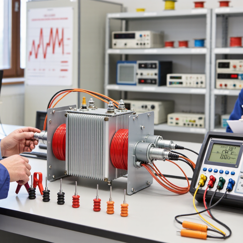
Define Current Transformer Accuracy and Its Key Performance Ratings
How to Measure Current Transformer Accuracy?
Current transformer accuracy describes how closely its secondary output represents the primary current. Engineers usually assess two errors: ratio error and phase displacement. Ratio error shows whether the measured current is too high or too low. Phase displacement shows the timing difference between primary and secondary currents. Small errors matter in energy metering, protection, and control systems.
Accuracy depends on more than the transformer label. Key ratings include accuracy class, rated burden, and frequency. Burden is the connected load, measured in volt-amperes. Excessive burden can increase ratio error and heating. Metering transformers often use classes such as 0.1, 0.2, or 0.5. Protection transformers need different ratings, including accuracy limit factor and knee-point voltage. The knee point indicates when the core begins to saturate sharply. Protection performance can collapse after that point.
Testing requires a stable current source, a calibrated reference transformer, and suitable measuring instruments. Apply several current levels, such as 5%, 20%, 100%, and 120% of rated current. Record the primary reference, secondary output, ratio error, and phase angle. Keep the specified burden connected during every test. Otherwise, the result may look better than real operation. Field conditions are rarely perfect. Cable resistance, loose terminals, and waveform distortion can change the readings. A practical test report should record temperature, frequency, burden, and test equipment uncertainty. One overlooked detail can weaken an otherwise careful conclusion.
How to Measure Current Transformer Accuracy?
Define Current Transformer Accuracy and Its Key Performance Ratings
The chart shows the maximum permitted current error at 100% of rated primary current for common metering current-transformer accuracy classes. A lower percentage indicates higher ratio accuracy.
Reference basis: IEC 61869-2 metering CT accuracy limits. Actual verification requires comparison with a calibrated reference system and measurement of ratio error and phase displacement under the specified burden and operating current.
Prepare the Equipment and Test Conditions for Accuracy Measurement
Before measuring current transformer accuracy, prepare a controlled setup rather than relying on a quick connection.
The test area should be dry, clean, and protected from accidental contact. Use an AC current source, calibrated reference instrument, burden resistor, polarity checker, and low-resistance test leads. Select equipment with calibration records traceable to recognized standards. Check every instrument’s range before applying current.
Small mistakes matter.
Confirm the transformer’s rated ratio, class, frequency, burden, and accuracy limit from its technical documentation.
The applied burden must match the intended operating condition, including lead resistance and connected instruments. Keep the source frequency stable, usually at the transformer’s rated value. Control current in measured steps. Record room temperature, humidity, winding identification, and test-point timing.
Ensure the secondary circuit remains closed whenever the primary carries current. Never improvise here.
Inspect terminals for loose hardware, oxidation, or damaged insulation before wiring the circuit. Verify polarity and continuity at low energy before beginning the accuracy run. If the transformer was previously energized, demagnetize it according to approved procedures.
Magnetic remanence can distort early readings.
I have seen stable equipment produce inconsistent results after a rushed setup. That assumption can fail. Repeat questionable points, document every adjustment, and preserve raw readings for independent review.
Measure Ratio Error and Phase-Angle Error Under Controlled Loads
How to Measure Current Transformer Accuracy?
Accurate current transformer testing begins with controlled loads, not field assumptions. Apply defined primary currents at 1%, 5%, 20%, 100%, and 120% of rating. Maintain the specified secondary burden and power factor. Real benches drift. Record temperature, wiring polarity, frequency, and instrument uncertainty before testing.
Calculate ratio error from the rated transformation ratio, measured primary current, and measured secondary current:
ratio error = (KnIs − Ip) / Ip × 100
Then compare the result with a calibrated reference transformer. IEC 61869-2 accuracy tables commonly specify a 0.2S class with ratio-error limits near ±0.2% at higher test currents. At 1% current, the permitted error is wider, often about ±0.75%. Low-current performance matters for lightly loaded feeders.
Measure phase-angle error with a synchronized reference system, recording the displacement between primary and secondary current waveforms. Express the result in minutes or milliradians.
For example, IEC 61869-2 lists tighter phase limits at normal current, while IEEE C57.13 provides comparable performance classes for instrument transformers. Keep it stable. A changing burden can imitate transformer error.
The test report should show every load point, not only the pass result. Our practical mistake is trusting one attractive reading; repeatability often reveals loose connections, waveform distortion, or an unsuitable reference standard.
Compare Test Results with the Applicable Accuracy Class Limits
How to Measure Current Transformer Accuracy?
Accurate current transformer testing begins with the applicable accuracy class, not with a single percentage. IEC 61869-2:2012 evaluates metering CTs at defined current points, including 5%, 20%, 100%, and 120% of rated current.
For a Class 0.5 CT, the ratio-error limits are typically ±1.5%, ±0.75%, ±0.5%, and ±0.5%, respectively. Phase displacement limits must also be checked.
A ratio result may pass while the phase result fails. That matters in revenue metering and power-quality calculations.
Compare every measured value with the limit for its exact test condition. Record primary current, secondary current, burden, frequency, polarity, temperature, and excitation state.
IEEE C57.13-2016 also links metering accuracy to the specified burden and power factor. A 5 VA test does not prove compliance at 15 VA. Small details matter.
Use a table, not memory. Mark each point as pass or fail, then investigate any margin below 20%.
Loose terminals, long test leads, residual magnetism, and incorrect burden settings can distort results.
I have seen clean-looking reports hide a wrong burden value. That mistake is easy to miss.
Standards also differ, so never apply an IEC limit to an IEEE classification without checking the relevant table.
The laboratory’s uncertainty should be reported beside the result, because a measured 0.48% error may not clearly pass a 0.5% limit. This is where judgment remains necessary.
Interpret the Results and Document the Current Transformer Performance
How to Measure Current Transformer Accuracy?
Measuring current transformer accuracy starts with controlled conditions. Record the primary current, secondary current, burden, frequency, temperature, and polarity. Use a calibrated reference transformer or precision current source. Compare the expected secondary output with the measured value. Calculate ratio error and phase displacement separately. The meter looked stable. That proves very little.
IEC 61869-2:2012 identifies metering accuracy classes such as 0.1, 0.2, 0.5, and 1.0. Its limits depend on current and burden conditions. IEEE C57.13-2016 also links transformer accuracy to rated burden and test points. These standards provide acceptance boundaries, not automatic certificates of performance. A passing result at rated current may still hide errors at low load. This is where many records become too optimistic.
Document every result in a traceable test sheet. Include the instrument serial numbers, calibration dates, wiring diagram, applied burden, test current, ratio error, and phase displacement. Preserve raw readings, not only the final pass or fail decision. Add photographs when wiring or polarity could be questioned later. I once found a small polarity mistake after reviewing an otherwise clean report. The numbers were precise, but the setup was wrong. Note unusual heating, unstable readings, or missing data openly. Reliability improves when uncertainty is recorded instead of quietly ignored.
How to Measure Current Transformer Accuracy? - Interpret the Results and Document the Current Transformer Performance
| Test Item |
Test Condition / Dimension |
Reference / Target |
Measured Result |
Evaluation |
Interpretation |
| Current transformer identification |
Application and accuracy class |
Metering CT, Class 0.5 |
Metering CT, Class 0.5 |
Recorded |
The selected limits are appropriate for a general-purpose energy-metering application. |
| Rated transformation ratio |
Primary current / secondary current |
400 A / 5 A |
400.18 A / 5.002 A equivalent |
Pass |
The measured ratio is close to the nominal 80:1 ratio. |
| Rated frequency |
Supply frequency during test |
50 Hz or 60 Hz |
50.00 Hz |
Pass |
The test frequency was stable and within the rated operating frequency. |
| Rated secondary burden |
External burden at 0.8 power factor |
5.0 VA |
4.96 VA |
Pass |
The connected burden is below the rated burden and does not overload the secondary circuit. |
| Insulation condition |
Insulation resistance at 500 V DC |
≥ 100 MΩ |
286 MΩ |
Pass |
The insulation resistance indicates no significant leakage path under the test condition. |
| Accuracy Performance Measurements |
| Primary Current |
Test Point |
Maximum Ratio Error |
Measured Ratio Error |
Evaluation |
Performance Comment |
| 20 A |
5% of rated current |
±1.50% |
+0.82% |
Pass |
The error is within the Class 0.5 limit at the low-current test point. |
| 80 A |
20% of rated current |
±0.75% |
+0.31% |
Pass |
The ratio error remains well below the applicable limit. |
| 400 A |
100% of rated current |
±0.50% |
−0.18% |
Pass |
The CT meets its stated metering accuracy at rated current. |
| 480 A |
120% of rated current |
±0.50% |
−0.24% |
Pass |
Accuracy remains compliant during the specified continuous overload test point. |
| Phase Displacement and Documentation |
| Primary Current |
Test Point |
Maximum Phase Displacement |
Measured Phase Displacement |
Evaluation |
Documentation Note |
| 20 A |
5% of rated current |
±90 minutes |
+46 minutes |
Pass |
Record the result because phase displacement affects active-energy measurement. |
| 80 A |
20% of rated current |
±45 minutes |
+19 minutes |
Pass |
The phase displacement is comfortably within the applicable limit. |
| 400 A |
100% of rated current |
±30 minutes |
−11 minutes |
Pass |
The CT introduces a small phase shift at rated current. |
| 480 A |
120% of rated current |
±30 minutes |
−14 minutes |
Pass |
The phase performance remains stable at the upper test point. |
| Test instrument uncertainty |
Expanded uncertainty, approximately 95% confidence |
≤ 0.10% ratio error |
0.06% ratio error |
Pass |
The measurement uncertainty is sufficiently smaller than the applicable accuracy limits. |
| Overall CT performance |
All tested current levels and phase-displacement points |
Meet Class 0.5 requirements |
All results within limits |
PASS |
The current transformer is suitable for the documented metering duty at the tested burden and frequency. |
Reference basis: The acceptance limits shown for the Class 0.5 metering transformer are commonly specified for accuracy testing at 5%, 20%, 100%, and 120% of rated primary current. Final acceptance should always follow the applicable transformer standard, purchase specification, and calibration procedure.
Conclusion
Measuring Current Transformer accuracy requires a controlled and systematic evaluation of how closely the transformer reproduces primary current on its secondary side. The process begins by defining key performance ratings, including the accuracy class, ratio accuracy, and phase-angle performance. Before testing, technicians should prepare a calibrated source, suitable measuring instruments, safe connections, and stable test conditions. The transformer is then tested under selected loads that represent its intended operating range.
During the measurement, the ratio error and phase-angle error are recorded at each controlled load and current level. These results are compared with the limits specified for the applicable accuracy class. Any deviation should be reviewed in relation to test conditions, wiring, burden, and instrument uncertainty. Finally, the findings should be documented clearly, including the equipment used, test points, recorded values, and pass-or-fail conclusions. This organized approach helps confirm reliable performance and provides traceable evidence for maintenance, commissioning, and future calibration decisions.