Toroidal Transformer Technical Articles and Insights
Technical Resources

Toroidal Transformer Blog & Articles

Expert guides, technical updates, and industry insights on Current & Power Transformers.

Resin Cast Current Transformers Insights
Industry Insights

Resin Cast CT Solutions

In-depth guides on high-accuracy resin cast measuring current transformers.

Toroidal Power Transformers Knowledge Base
Engineering Knowledge

Toroidal Power Design

Articles detailing compact, low-noise toroidal power transformers for OEM applications.

0%

Choosing a Ring Type Current Transformer requires more than comparing ratios and prices. The right choice depends on accuracy class, burden, insulation level, fault current, window size, and installation space. A small panel opening can quickly become a serious engineering limitation.

MarketsandMarkets reported that the global current transformer market was projected to grow from approximately USD 2.2 billion in 2023 to USD 3.1 billion by 2028. This growth reflects wider adoption in smart grids, industrial monitoring, and renewable-energy systems. IEC 61869-2 defines key requirements for instrument transformers, including accuracy, insulation, and temperature performance. IEEE C57.13 also remains an important reference for transformer ratings and testing. These standards matter in real installations, where a few millimeters of clearance may affect safety.

Power-system engineer Paul Gill has stated, “A current transformer is only as accurate as the burden connected to it.” His observation is practical, not merely theoretical. Excessive secondary burden can increase measurement error and cause saturation during faults. Engineers should therefore verify cable length, relay impedance, short-circuit current, and continuous load before selecting a model. Ring core material matters too. Nanocrystalline cores can support high sensitivity, while traditional silicon steel may offer a more economical solution. However, no material is automatically best. The application decides. A catalog value can look excellent, yet perform poorly after installation. This guide explains how to choose a Ring Type Current Transformer with clearer technical judgment, reliable references, and a little healthy skepticism.
How to Choose a Ring Type Current Transformer?

Understanding the Structure and Function of a Ring Type Current Transformer

How to Choose a Ring Type Current Transformer?

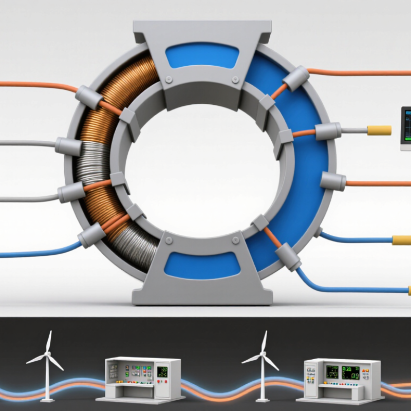
A ring type current transformer uses a circular magnetic core, a primary conductor, and a secondary winding. The conductor passes through the center, creating the primary circuit. The secondary winding then produces a smaller current for meters, protection devices, or control systems. This structure provides electrical isolation and supports safer measurement. Its accuracy depends on the core material, winding quality, current ratio, and connected burden.

When choosing one, measure the cable diameter and required opening size carefully. A tight fit can complicate installation and may damage insulation. Select a ratio that matches the normal operating current, not only the maximum load. Check accuracy class, rated burden, insulation level, and frequency range. For existing cables, a split-core design can reduce downtime. However, its hinged structure may introduce small measurement errors if the core does not close fully. Never leave the secondary circuit open while current flows. That condition can create dangerous voltage.

Tips: Confirm the conductor position before tightening the enclosure. Keep the cable centered when possible. Compare the transformer rating with the actual meter input. Do not rely on appearance alone. A larger ring is not always better. Installation records should include ratio, wiring direction, and test results. One detail is easy to miss: polarity marks matter during energy and protection measurements. Recheck them before energizing the system.

Identifying the Electrical Requirements for Your Current Transformer

Choosing a ring type current transformer starts with the electrical requirements, not the enclosure size. Record the system voltage, frequency, maximum load current, and prospective short-circuit current. A site survey should also note cable diameter, installation space, and whether the conductor can be disconnected. Small details matter.

Select the primary-to-secondary ratio from measured demand, not only the nameplate rating. A 400/5 A transformer may perform poorly when normal current stays near 20 A. Its useful measurement range could become too narrow. Check the connected burden in volt-amperes, including meters, relays, and cable losses. The selected burden must remain below the transformer’s rated burden. For protection circuits, confirm the knee-point requirement and saturation behavior. IEC 61869-2 provides key requirements for instrument transformers, including accuracy and testing.

Accuracy also depends on purpose. Revenue measurement usually needs a tighter accuracy class than basic monitoring. The IEA’s Electricity 2024 report expects global electricity demand to grow by more than 4% in 2024, increasing pressure on measurement and distribution equipment. That trend makes flexible monitoring valuable, but it does not replace proper sizing. IEEE power-system guidance also emphasizes fault-duty evaluation before equipment selection. I would recheck the calculation against real load data, because design estimates are often optimistic. This check is easy to overlook. Finally, verify insulation level, ambient temperature, indoor or outdoor use, and safe secondary-circuit practice before approval.

Selecting the Correct Core Size, Ratio, and Accuracy Class

How to Choose a Ring Type Current Transformer?

Selecting a ring type current transformer starts with the core window. Measure the conductor, insulation, bending radius, and clearance before choosing the opening diameter. A tight fit can damage insulation and complicate installation. An oversized core may reduce measurement sensitivity, especially at low current. Leave practical clearance, not excessive space. IEC 61869-2 identifies standard measuring classes such as 0.1, 0.2, 0.5, and 1, with performance tested at specified burdens and currents.

Choose the ratio from the real operating range, not only the nameplate rating. For example, a 200/5 CT produces 5 amperes at 200 amperes primary current. If the circuit normally carries 35 amperes, that ratio may waste resolution. Check peak load, continuous load, and possible future expansion. The connected burden includes meter impedance, relay inputs, and lead resistance. Even a short cable can matter. IEEE C57.13 requires accuracy evaluation against defined burden and current conditions, so a ratio is never meaningful by itself.

Accuracy class depends on the application. Revenue metering usually demands tighter limits than basic monitoring. Protection CTs require different behavior during faults and may need knee-point or excitation data. Confirm those values from test certificates. In practice, installers sometimes select a high class without checking cable burden. I have seen that assumption create avoidable errors. It sounds careful, but it is incomplete. Record the ratio, class, burden, frequency, insulation level, and installation position before ordering.

Checking Insulation, Burden, and Installation Conditions

How to Choose a Ring Type Current Transformer?

Checking Insulation, Burden, and Installation Conditions

Choosing a ring type current transformer starts with insulation, not only current ratio. Check the circuit’s highest operating voltage and required insulation level. The transformer must tolerate the system voltage, temperature, and surrounding moisture. Inspect the insulation surface for cracks, dust, or compressed sections before installation. Small damage can become serious under electrical stress. Keep the secondary circuit closed or properly connected during operation. An open secondary can create dangerously high voltage.

Burden is equally important. Add the meter, relay, terminal, and cable resistance in the secondary circuit. Compare this total with the transformer’s rated burden in volt-amperes. Long cables may quietly increase the load. A correct ratio cannot compensate for excessive burden. Accuracy class also matters, especially when the transformer supports protection rather than routine measurement. Field checks sometimes reveal that the selected burden was based on a short cable estimate. That assumption deserves review.

Installation conditions can change performance. Measure the conductor diameter before ordering, and leave enough window clearance for safe fitting. Center the conductor when practical. Avoid sharp cable bends near the ring and keep the transformer away from strong heat sources. Confirm the mounting position, secondary terminal access, and grounding arrangement. I have seen technically suitable transformers fail during installation because the enclosure was too tight. The specification was right, but the space was wrong. Make a final inspection with the circuit isolated and the wiring clearly identified.

How to Choose a Ring Type Current Transformer?

Checking insulation, burden, and installation conditions

1. Check Insulation

Select an insulation level suitable for the system voltage, grounding method, temporary overvoltage, and installation environment. For medium-voltage applications, verify the rated insulation level and impulse withstand rating on the CT data sheet.

2. Calculate Burden

Add the burden of meters, relays, terminals, and secondary wiring. At a 5 A secondary rating, the approximate voltage requirement is V = VA ÷ 5. Keep the connected burden below the CT rated burden.

3. Confirm Installation

Check the ring aperture, conductor or busbar size, mounting clearance, polarity, cable routing, and access for testing. Never leave a current-transformer secondary open while the primary is energized.

The chart shows the secondary voltage associated with common rated burdens for a 5 A secondary current. Actual selection must be verified against the CT accuracy class, frequency, fault-current requirement, insulation rating, and applicable electrical standards.

Comparing Safety Features, Standards, and Maintenance Requirements

Choosing a ring type current transformer requires more than matching a ratio. Safety features deserve equal attention. A secondary circuit must never remain open while the primary carries current. Dangerous voltage can develop quickly. Select a model with accessible shorting terminals, clear polarity marks, strong insulation, and a secure enclosure. Split-core designs also need a reliable locking mechanism. A small air gap can affect accuracy.

Check the applicable standard before purchasing. IEC 61869-2 and IEEE C57.13 define important performance requirements, including accuracy, insulation, burden, and thermal limits. Local electrical codes may add installation rules. Confirm the required accuracy class, rated insulation level, and short-time thermal current. Field experience shows that a correct ratio does not guarantee correct measurement. Cable position and phase direction matter. I have seen good equipment produce poor readings after careless installation.

Tips: De-energize equipment whenever possible. Never rely on insulation alone. Inspect terminals, seals, cracks, and discoloration during scheduled maintenance. Tighten connections according to the manufacturer’s specified torque, not personal judgment. Use thermal imaging to find unusual heating, then investigate the cause. Keep test records with the installation date, readings, and calibration details. A checklist helps, but it can still miss loose hardware or moisture. Review it with another qualified technician when conditions seem unusual.

How to Choose a Ring Type Current Transformer? - Comparing Safety Features, Standards, and Maintenance Requirements
Selection Criterion Solid-Core Ring CT Split-Core Ring CT Practical Selection Guidance
Core Construction Continuous magnetic core with a fixed window. The conductor normally passes through the opening during initial installation. Hinged or separable magnetic core that can be fitted around an existing conductor without disconnecting the conductor. Choose a solid-core design for new installations where the conductor can be routed through the CT. Choose a split-core design for retrofit work where cable removal is difficult.
Typical Measurement Accuracy Usually provides more consistent magnetic coupling and lower measurement error than a split-core design of similar size. Accuracy depends strongly on core alignment, closure pressure, cleanliness of mating surfaces, and conductor position. A small residual air gap can increase error. Use the manufacturer’s declared accuracy class and test data for the complete assembly. Do not assume that a split-core CT has the same accuracy as a solid-core model with the same ratio.
Common Accuracy Classes Metering classes may include IEC classes such as 0.2, 0.5, or 1; protection classes may include 5P or 10P, subject to the applicable standard and design. Available classes vary by construction and application. Portable or retrofit split-core units are commonly selected for monitoring, but protection applications require specific certified performance. Match the class to the application: revenue or high-accuracy metering requires stricter limits than general energy monitoring. Confirm the required class at the specified burden and frequency.
Rated Current and Ratio Common ratios include 100/5 A, 200/5 A, 400/5 A, and 800/5 A, but the correct ratio must be selected from the actual primary current and operating range. Available ratios depend on the model and window size. The conductor must fit correctly and remain within the CT’s rated primary current and installation limits. Select a ratio that avoids continuous saturation during normal operation while still providing useful resolution at the minimum expected load.
Secondary Output Common outputs are 1 A or 5 A for protection and metering circuits. Some electronic monitoring CTs provide a low-level voltage or current output. May provide 1 A or 5 A secondary current, or a low-level output intended for a dedicated measuring device. Outputs are not interchangeable without checking the instrument requirements. Verify secondary current, polarity, burden, insulation rating, and connector arrangement before connecting the CT to a meter, relay, or transducer.
Open-Secondary Safety Critical
An energized CT secondary must not be left open-circuit. Dangerous voltage can develop across the secondary terminals, creating shock and insulation-failure hazards.
Critical
The same open-secondary hazard applies. Split-core construction does not remove the need for a shorting link, test switch, or suitable burden.
Install a short-circuiting terminal block or approved test switch. Short the secondary before disconnecting any burden or measuring device, and follow the site isolation procedure.
Installation Safety Normally requires de-energizing and isolating the circuit before the conductor is passed through the CT. Mechanical clearance and insulation coordination must be maintained. Can reduce conductor-disconnection work, but installation around energized conductors still requires an electrically safe work procedure, suitable PPE, insulated tools, and competent personnel. De-energization is the preferred method whenever practicable. A split-core CT should not be treated as permission to work on energized equipment without an approved risk assessment.
Conductor Position Centering the conductor in the window generally improves accuracy and reduces the effect of nearby magnetic fields. Centering is especially important because off-center placement and an imperfect core closure can increase ratio and phase-angle errors. Use the manufacturer’s window-size and conductor-position instructions. Do not force oversized conductors through the aperture or place multiple conductors in one CT unless specifically permitted.
Burden Compatibility The connected meter, relay, wiring, and terminals must remain within the CT’s rated burden, commonly expressed in VA or ohms. Long retrofit wiring runs and additional terminal connections can create a significant burden relative to the CT’s rating. Calculate the total secondary burden, including cable resistance. An excessive burden can increase error and may cause unacceptable performance during fault conditions.
Protection Performance Suitable protection CTs can be specified using parameters such as accuracy limit factor, composite error, knee-point voltage, or excitation characteristics, depending on the standard and protection scheme. Only use a split-core CT for protection when its declared protection performance has been verified for the relay, fault level, burden, and system configuration. Do not substitute a general-purpose monitoring CT for a protection CT. Protection applications require a coordinated design review and documented test data.
Applicable International Standards IEC 61869-1 provides general requirements for instrument transformers, while IEC 61869-2 covers additional requirements for current transformers. IEEE C57.13 is also widely used for instrument transformer requirements. The same standards may apply when the CT is within their scope. The product documentation should identify the tested standard, rated insulation level, accuracy class, and applicable environmental ratings. Use the standard required by the project, country, utility, or authority having jurisdiction. IEC and IEEE requirements should not be treated as automatically equivalent without engineering verification.
Insulation and Dielectric Requirements Check rated insulation level, power-frequency withstand, impulse withstand where applicable, creepage, clearance, and enclosure requirements. Check the same electrical requirements, plus the integrity of the hinge, latch, split line, insulation barriers, and any exposed secondary terminals. The CT’s voltage rating must be suitable for the system voltage and installation category. Mechanical enclosure protection does not replace electrical insulation coordination.
Ingress Protection and Environment Enclosure ratings vary by design. Outdoor or contaminated locations require suitable protection against moisture, dust, chemicals, ultraviolet exposure, and temperature extremes. The split line and hinge area require particular attention to sealing and contamination. Frequent opening can reduce the effectiveness of protective seals on some designs. Confirm the declared IP rating or equivalent enclosure classification, operating temperature range, humidity limits, and suitability for indoor or outdoor installation.
Maintenance Frequency Typically requires periodic visual inspection and electrical testing according to the site’s maintenance program, equipment criticality, and applicable regulations. Requires the same general inspection plus regular checks of core closure, hinge condition, latch security, mating-surface cleanliness, and physical alignment. There is no universal interval for every installation. Establish the interval through the manufacturer’s instructions, risk assessment, operating environment, and condition-monitoring results.
Routine Inspection Items Inspect mounting hardware, insulation, terminal tightness, corrosion, overheating marks, cable condition, labeling, and evidence of mechanical damage. Inspect all solid-core items plus hinge wear, latch operation, core-face cleanliness, closure gap, cracks, and movement caused by vibration. Inspection should be performed under an approved electrical safety procedure. Secondary circuits must be controlled to prevent accidental open-circuit operation.
Testing and Verification Depending on the application, tests may include insulation resistance, ratio, polarity, excitation, winding resistance, burden verification, and secondary injection testing. Perform the applicable tests with the core fully closed and correctly installed. Ratio and accuracy checks should reflect the actual conductor position and connected burden. Use calibrated test equipment and compare results with factory data or commissioning records. Investigate unexplained changes rather than relying only on visual inspection.
Best-Fit Applications New switchboards, motor-control centers, protection panels, revenue metering, and installations where repeatable accuracy and robust mechanical construction are priorities. Energy monitoring, load studies, temporary measurements, building retrofits, and installations where conductor disconnection would require substantial outage work. For critical protection or high-accuracy metering, prioritize certified performance and testability over installation convenience.
Main Advantages Consistent core geometry, generally better accuracy stability, strong mechanical integrity, and suitability for permanent metering or protection circuits. Fast retrofit installation, reduced conductor disturbance, and easier addition to existing cable systems where access is limited. Evaluate total lifecycle cost, including outage time, installation labor, testing, future access, and the consequences of measurement error.
Main Limitations Usually requires conductor access or circuit shutdown during installation and may require more installation space or labor. More sensitive to closure quality, alignment, contamination, vibration, and mechanical wear; some models have lower accuracy or limited protection capability. Choose split-core only when its documented accuracy, insulation, short-circuit safety, and environmental ratings meet the complete application requirements.
Safety note: A current transformer secondary can develop hazardous voltage when the primary is energized and the secondary circuit is open. Always follow the applicable electrical safety rules, isolate equipment whenever practicable, and use an approved shorting arrangement before disconnecting secondary wiring.

FAQS

What electrical information should be collected before selecting a ring type current transformer?

Record system voltage, frequency, maximum load current, and prospective short-circuit current. Measure cable diameter and available installation space. Also check whether the conductor can be disconnected. Small details matter.

How should the primary-to-secondary ratio be selected?

Base the ratio on measured demand, not only the equipment nameplate. A 400/5 A transformer may perform poorly when normal current stays near 20 A. The measurement range may become too narrow. Do not guess.

What is the connected burden, and why does it matter?

Connected burden includes meters, relays, and cable losses. Calculate the total burden in volt-amperes. It must remain below the transformer’s rated burden. Cable length can change the result.

Does the required accuracy class depend on the application?

Yes. Revenue measurement usually requires tighter accuracy than basic monitoring. Protection circuits also need suitable knee-point and saturation performance. A correct ratio alone does not guarantee accurate readings.

What safety features should a ring type current transformer include?

Look for accessible shorting terminals, clear polarity marks, strong insulation, and a secure enclosure. Split-core models need a reliable locking mechanism. Small gaps matter.

Why must the secondary circuit avoid open operation?

Never leave the secondary circuit open while primary current flows. A dangerous voltage can develop quickly. De-energize the equipment whenever possible, and follow approved electrical procedures.

Which installation details can affect measurement accuracy?

Cable position, phase direction, and split-core alignment can affect readings. Even good equipment may measure poorly after careless installation. Recheck the air gap and locking mechanism.

What should be checked during maintenance?

Inspect terminals, seals, cracks, discoloration, and signs of moisture. Tighten connections using the specified torque. Thermal imaging can reveal unusual heating, but the cause still needs investigation.

What records should be kept after installation?

Keep the installation date, test readings, calibration details, and inspection results. A checklist helps, but it can miss loose hardware. When conditions seem unusual, ask another qualified technician to review the work.

Conclusion

Choosing the right Ring Type Current Transformer requires a clear understanding of both its construction and operating purpose. Its ring-shaped magnetic core surrounds a conductor, allowing current to be measured safely and accurately without directly interrupting the primary circuit. Begin by identifying the system voltage, primary current, secondary output, frequency, phase configuration, and intended application. These electrical requirements provide the foundation for selecting a suitable transformer.

Next, confirm the core size so the conductor can pass through easily, then choose an appropriate transformation ratio and accuracy class for metering, monitoring, or protection. It is also important to evaluate insulation performance, rated burden, temperature, environmental conditions, and available installation space. Safety features such as secure terminals, protective enclosures, and provisions against an open secondary circuit should be considered. Finally, review applicable technical standards and maintenance needs, including inspection, connection checks, and periodic performance verification, to ensure reliable and long-term operation.


Ethan

Ethan

Ethan is a dedicated marketing professional with a passion for driving brand engagement and enhancing customer experience through strategic content development. With a deep understanding of the company's core offerings, he excels in showcasing the unique advantages of our products and services. His......